Companion repository: Embedded-Systems-II---AoA-of-Multidirectional-Audio-System
The problem: gaps in the stream
An angle-of-arrival system lives or dies by the continuity of its audio streams. In the AoA project — a four-microphone array on the TM4C123GH6PM (ARM Cortex-M4F) with precision microphones at −44 dBV/Pa sensitivity and 40 dB of amplification — direction is estimated from time-difference-of-arrival between mic pairs, computed by cross-correlating the captured signals. Cross-correlation assumes the samples it compares were taken at uniform intervals with no gaps. Every dropped sample shifts the apparent phase between channels, and a few missing samples can move the computed angle more than the noise floor should allow. The sampling path has to be honest: every sample, on time, no exceptions.
The naive way to capture ADC data is an interrupt per sample: the ADC finishes a conversion, fires an interrupt, the ISR reads the result register and stores it. At low rates this works fine. As the sample rate climbs, it collapses — and understanding exactly why it collapses is the first step toward the fix.
(A note on the code: the snippets below are illustrative reconstructions in the TivaWare style, matching the documented design — DMA buffers moving ADC microphone data to memory without CPU involvement, to prevent data loss and enable continuous processing. They show the pattern, not verbatim repo lines.)
Why polling and ISR-per-sample collapse
Consider what an interrupt-per-sample actually costs. Each conversion triggers: interrupt entry (register stacking, vector fetch), the ISR body (read ADC result, store to buffer, maybe increment an index and check a bound), and interrupt exit (unstacking, pipeline refill). On a Cortex-M4F that’s dozens of cycles of overhead per sample before you’ve done any useful work — and the useful work (storing the sample) is the smallest part.
Two failure modes follow:
-
CPU saturation. The interrupt rate rises linearly with the sample rate while the useful work per sample stays fixed. Past some rate, the CPU spends all of its time entering and leaving the ADC ISR. Nothing else runs — not the cross-correlation, not the UART CLI, nothing. The system doesn’t degrade gracefully; it locks into servicing interrupts.
-
Jitter. Even below saturation, per-sample ISRs compete with every other interrupt in the system. When a higher-priority interrupt (or a critical section with interrupts disabled) delays the ADC ISR, the sample is still converted on time by hardware — but the handling is late, and if the next conversion completes before the previous result was read, the result register is overrun and a sample is lost silently. Your cross-correlation now has a gap it doesn’t know about. This is the worst kind of failure: the data looks continuous but isn’t.
Polling is strictly worse — the CPU spins waiting for the conversion flag, which is 100% utilization by construction.
DMA fundamentals: the peripheral talks to memory directly
Direct Memory Access is a separate bus master that moves data between a peripheral and memory without the CPU. You configure it once: source address (the ADC result register), destination address (a buffer in SRAM), transfer count, and the trigger (ADC conversion complete). Then the ADC converts, and the DMA controller quietly writes each result into memory and increments the destination pointer. The CPU is free — or asleep — the entire time.
This is the documented design of the AoA system: DMA buffers move ADC microphone data to memory without CPU involvement, which prevents data loss and enables continuous processing. But a single linear buffer only defers the problem. When the DMA reaches the end of the buffer, it stops (or wraps and overwrites data the CPU hasn’t processed yet). You need a scheme where the DMA always has somewhere to write while the CPU always has something to process. That’s the double buffer.
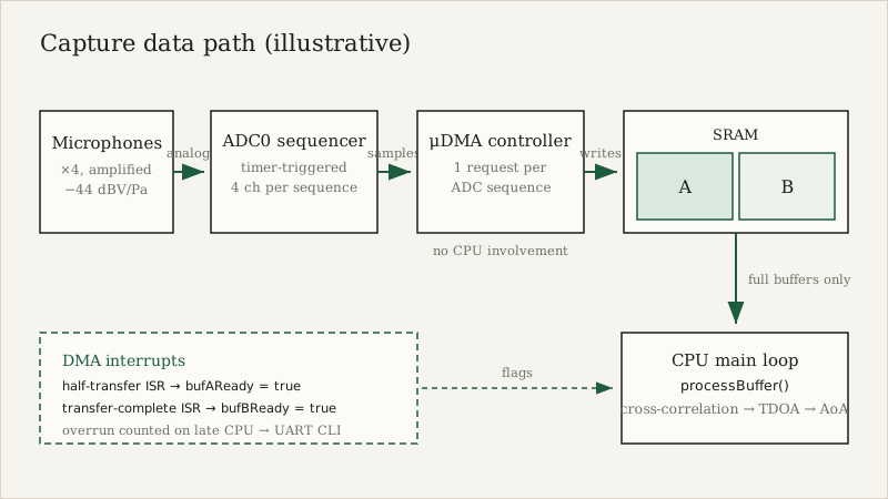 Figure — Capture data path: samples move from the microphones to SRAM via DMA with no CPU involvement; the CPU sees only full, gap-free buffers. Illustrative.
The ping-pong pattern
Allocate two buffers, A and B. Configure the DMA in circular mode over the combined region (A followed by B). The DMA fills A while the CPU processes B; when the DMA finishes A, it moves to B while the CPU processes A; then it wraps. The two agents never touch the same buffer at the same time — that’s the invariant the whole design protects.
The DMA controller gives you exactly the two interrupts you need:
- Half-transfer interrupt: the DMA just finished buffer A and is starting B. The CPU may now process A.
- Transfer-complete interrupt: the DMA just finished B and is wrapping to A. The CPU may now process B.
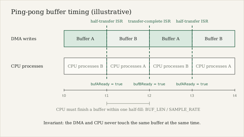 Figure — Ping-pong timing: the DMA fills one buffer while the CPU processes the other, with the two DMA interrupts marking the swap instants. Illustrative.
Here’s the setup in TivaWare style, for one microphone channel:
#define BUF_LEN   512          // samples per half-buffer (see sizing, below)
#define NUM_CH    4            // four microphones

// Interleaved or per-channel; here per-channel for clarity
static uint16_t dmaBufA[NUM_CH][BUF_LEN];
static uint16_t dmaBufB[NUM_CH][BUF_LEN];

// Flags set by ISRs, consumed by the processing loop.
// volatile: written in interrupt context, read in main context.
static volatile bool bufAReady = false;
static volatile bool bufBReady = false;

void initDmaCapture(void)
{
    SysCtlPeripheralEnable(SYSCTL_PERIPH_UDMA);
    uDMAEnable();
    uDMAControlBaseSet(dmaControlTable);   // 1024-byte aligned control table

    SysCtlPeripheralEnable(SYSCTL_PERIPH_ADC0);
    // ADC0 sequencer 0: 4 samples (one per mic channel), triggered by timer
    ADCSequenceConfigure(ADC0_BASE, 0, ADC_TRIGGER_TIMER, 0);
    ADCSequenceStepConfigure(ADC0_BASE, 0, 0, ADC_CTL_CH0);
    ADCSequenceStepConfigure(ADC0_BASE, 0, 1, ADC_CTL_CH1);
    ADCSequenceStepConfigure(ADC0_BASE, 0, 2, ADC_CTL_CH2);
    ADCSequenceStepConfigure(ADC0_BASE, 0, 3, ADC_CTL_CH3 | ADC_CTL_IE | ADC_CTL_END);
    ADCSequenceEnable(ADC0_BASE, 0);
    ADCSequenceDMAEnable(ADC0_BASE, 0);     // each sequence -> one DMA request

    // uDMA channel for ADC0 SS0: basic mode over A then B is not enough;
    // use auto-request ping-pong or a single circular transfer over the
    // concatenated region with half-transfer interrupt at the midpoint.
    uDMAChannelAttributeDisable(UDMA_CHANNEL_ADC0,
        UDMA_ATTR_ALTSELECT | UDMA_ATTR_USEBURST |
        UDMA_ATTR_HIGH_PRIORITY | UDMA_ATTR_REQMASK);
    uDMAChannelControlSet(UDMA_CHANNEL_ADC0 | UDMA_PRI_SELECT,
        UDMA_SIZE_16 | UDMA_SRC_INC_NONE | UDMA_DST_INC_16 |
        UDMA_ARB_4);
    uDMAChannelTransferSet(UDMA_CHANNEL_ADC0 | UDMA_PRI_SELECT,
        UDMA_MODE_BASIC,
        (void *)(ADC0_BASE + ADC_O_SSFIFO0),
        &dmaBufA[0][0],
        NUM_CH * BUF_LEN * 2);             // A then B, contiguous
    uDMAChannelEnable(UDMA_CHANNEL_ADC0);
    uDMAChannelIntEnable(UDMA_CHANNEL_ADC0);
    IntEnable(INT_UDMA);

    TimerConfigure(TIMER0_BASE, TIMER_CFG_PERIODIC);  // sample-rate timer
    TimerLoadSet(TIMER0_BASE, TIMER_A, SysCtlClockGet() / SAMPLE_RATE);
    TimerControlTrigger(TIMER0_BASE, TIMER_A, true);  // trigger ADC
    TimerEnable(TIMER0_BASE, TIMER_A);
}
A note on the transfer mode: many DMA controllers (including the TM4C123’s μDMA) don’t have a true “circular with half-transfer interrupt” mode. The standard trick is ping-pong mode (primary + alternate control structures that swap automatically) or a single basic transfer over the concatenated A+B region with the controller’s transfer-complete at the midpoint faked by chaining. Either way, the two interrupts you need are “first half done” and “second half done.” The exact register choreography varies by vendor; the invariant — DMA owns one half, CPU owns the other — is universal.
The interrupt handlers are deliberately trivial. An ISR should signal, never compute:
void uDMAIntHandler(void)
{
    uint32_t status = uDMAIntStatus();
    uDMAIntClear(status);

    if (halfTransferComplete()) {       // DMA finished buffer A, now filling B
        if (bufAReady) {
            overrunCount++;             // CPU didn't finish A in time — data lost
        }
        bufAReady = true;
        // re-arm the DMA destination for A (ping-pong) or continue (circular)
        rearmDmaForBufferA();
    }
    if (transferComplete()) {           // DMA finished buffer B, wrapping to A
        if (bufBReady) {
            overrunCount++;
        }
        bufBReady = true;
        rearmDmaForBufferB();
    }
}
Two details matter here. First, the overrun check: if the ready flag is already set when the DMA finishes a buffer, the CPU didn’t process the previous contents in time, and the DMA is about to overwrite them. Count it. An overrun counter exposed over the UART CLI (the AoA project’s monitoring interface) turns silent data corruption into a visible, debuggable metric. Second, the ISR sets flags and rearms — nothing else. All signal processing happens in the main loop:
int main(void)
{
    initHw();
    initDmaCapture();
    initUart0();          // CLI: average, level, aoa, tdoa, fail commands

    while (1) {
        if (bufAReady) {
            bufAReady = false;
            processBuffer(dmaBufA);   // filter, detect, cross-correlate
        }
        if (bufBReady) {
            bufBReady = false;
            processBuffer(dmaBufB);
        }
        // optionally: sleep until the next DMA interrupt
    }
}
processBuffer is where the cross-correlation for TDOA lives — but note what the architecture bought you: the processing code has no idea the DMA exists. It receives a full, contiguous, gap-free buffer of samples. The sampling path and the processing path are decoupled by the ping-pong invariant.
The failure modes, honestly
Overrun: processing slower than the fill rate. This is the fundamental constraint, and it has exact math. The DMA fills one half-buffer every BUF_LEN / SAMPLE_RATE seconds. The CPU must finish processing a half-buffer within that window, every time, worst case. So:
BUF_LEN ≥ 2 × SAMPLE_RATE × T_process_worst
where T_process_worst is the worst-case — not average — processing time for one half-buffer. (The factor of 2: you need one full half-buffer of headroom because the DMA is filling the other half while you process.) If your cross-correlation occasionally takes 3× its typical time (cache miss storm, a loud transient that trips the detection path), size for that, not the typical. Overruns you sized for don’t happen; overruns you hoped wouldn’t happen will, at the demo.
Note what this equation says about the common instinct to shrink buffers for lower latency. Halving BUF_LEN halves your processing deadline. Latency and robustness trade directly; the honest choice is to compute the deadline from measured worst-case processing time and size up from there.
Cache coherency. On Cortex-M7 parts with data cache (and as a habit worth building on any M-series), the DMA writes to SRAM behind the CPU’s cache. If the CPU has a stale cached copy of the buffer line, it will process old data. The fix: invalidate the D-cache for the buffer region after the DMA completes it and before the CPU reads it — or place DMA buffers in a non-cacheable memory region via the MPU. The TM4C123’s M4F has no data cache, so this specific project doesn’t hit it — but the pattern transfers verbatim to every M7 you’ll ever use, and “works on M4, corrupts silently on M7” is a classic porting trap.
Alignment and burst constraints. DMA controllers move data in bursts and often require source/destination alignment matching the transfer size. A uint16_t buffer at an odd address, or a transfer count that isn’t a multiple of the arbitration size, will fault or silently misbehave depending on the controller. Align DMA buffers explicitly (__attribute__((aligned(4))) or the control-table alignment the μDMA demands — 1024 bytes for the table itself) and assert the constraints at compile time where you can.
Interrupt priority. The DMA completion interrupt must preempt the processing path’s interrupts but never be blocked by a long critical section in the main loop. If your processing code disables interrupts for longer than a half-buffer fill time, you’ve built an overrun machine. Keep critical sections short, or better, make the ready flags the only shared state and never disable interrupts around processing.
Sizing buffers honestly
Pulling it together, buffer sizing is a small engineering calculation, not a guess:
- Measure
T_process_worst: instrumentprocessBufferwith a timer, run it against worst-case input (maximum event rate, noisiest signal), take the max over a long run. - Compute the minimum half-buffer:
BUF_LEN_min = 2 × SAMPLE_RATE × T_process_worst, then round up to a power of two or whatever your FFT/correlation length wants. - Check memory: 2 × BUF_LEN × channels × bytes-per-sample must fit SRAM alongside everything else. Four channels of 16-bit samples at 1024 per half-buffer is 16 KB — fine on the TM4C123’s 32 KB SRAM, but it does concentrate the mind.
- Check latency: a full buffer (A+B) is your detection latency floor. If the application needs an AoA estimate within X ms of the sound arriving, the total buffer time
2 × BUF_LEN / SAMPLE_RATEmust be under X. If the math doesn’t close, you need faster processing, not smaller buffers — smaller buffers just move the failure to overruns.
The principle
DMA double-buffering is really two ideas composed: the DMA makes sampling independent of CPU load, and the ping-pong invariant makes processing independent of sampling. Each side gets a clean contract — the DMA always has a buffer to fill, the CPU always has a complete buffer to process — and the only shared state is two flags and an overrun counter. The cross-correlation doesn’t know or care how its samples arrived; it just sees gap-free data, which is the entire point.
And the honest summary: DMA doesn’t make your processing faster. It makes your sampling honest — every sample captured, on time, whether or not the CPU was busy. In a system whose output is a direction computed from phase differences between channels, honest sampling isn’t an optimization. It’s the difference between a measurement and a guess.